Project Circuit Search

Custom Search
WELCOME To PROJECT CIRCUIT DESIGN

Sponsor Link

Showing posts with label Controller. Show all posts

Small DC Motor Speed Controller Circuit

|

Electric motor has been widely used as motion control, and many  type of motor controllers  have been designed to provide variable speed drives for the motor. The best controller is the servo controller, where is a precise speed control is implemented using a speed sensor in the feedback path.  The circuit of the motor controller is in this article use a novice method to control the motor. It uses the back electromotive force (back-emf)  sensing to keep the motor rpm at a fairly constant value. This is the figure of the circuit;


his motor speed controller is suitable for 3V battery operated devices like portable cassette player or portable audio cd player, keeping the motor rpm to be constant. This circuit is not a PWM motor control, so the motor power should be low power type to avoid excessive heating. This circuit only works for small  dc motor, it won’t work for ac motor. The motor driver at the final output is integrated in the IC chip, ideal for low component count solution.  Unlike a servo controller, the motor speed is not kept at very tight reference because the feedback is not coming from a speed sensor, but only detect the dc motor’s electromotive force generation to maintain the motor speed at a fairly constant value. [Circuit diagram source:  STMicroelectronics Application Notes]

Positive Low Voltage Hot Swap Controller Using Power Limiter

|

This is the design circuit of Positive Low Voltage Hot Swap Controller circuit with Power Limiter. This circuit gives intelligent control of the power supply voltage to the load during removal and insertion of circuit cards from “hot” power sources or a live system backplane. This is the figure of the circuit;


This circuit uses The LM25069 that gives in-rush current control to limit system voltage transients and droop. This circuit has programmable current limit and power dissipation in the external series pass N-Channel MOSFET. So, operation will in the Safe Operating Area (SOA). The POWER GOOD output is used to indicate voltage is within 1.3V of the input voltage. this circuit has The programmable input under-voltage and over-voltage, programmable lockout levels and programmable hysteresis, programmable the initial insertion delay time and programmable fault detection time. The LM25069-2 automatically restarts at a fixed duty cycle, and LM25069-1 latches off after a fault detection. The LM25069 has 10 pin MSOP package.  Refer to its datasheet for selecting the proper external components values that suits your need. [Circuit diagram source: National Semiconductor]

Positive High-Voltage Hot Swap Controller with Power Limiter

|

This is the figure of the Positive High-Voltage Hot Swap Controller circuit with Power Limiter. This circuit uses the TPS2491 or TPS2490 because both of them have some advantages. The advantages of the TPS2491 and TPS2490 are positive high voltage, easy-to-use and has 10-pin Hot Swap Power Manager™ devices. 10-pin Hot Swap Power Manager™ devices will ensure the safety in driving an external N-channel MOSFET switch. This is the figure of the circuit;
 

TPS2491 and TPS2490 usually are used in electronic circuit breaker protection, interfacing to down-stream dc-to-dc converters, power feed protection inrush current limiting and controlled load turn-on. This circuit has the current limiter and power limiter. Both of them ensure that the external MOSFET operates inside a selected safe operating area (SOA) under the harshest operating conditions. Besides that, these devices are space-saving 10-pin MSOP package, available in a small and significantly reduce the number of external devices, saving precious board space. [Circuit diagram source: Texas Instruments Application Note]

Closed Loop Automatic Power Control for RF Applications Circuit

|

This is a circuit design of Closed-Loop Automatic Power Control for RF Applications. The circuit uses a log detector (AD8318) and a VGA (ADL5330). This circuit has high temperature stability because of the high temperature stability of the AD8318. The AD8318 also ensures the same level of temperature stability at the output of the ADL5330 VGA.

The ADL5330 is converted from an open-loop variable gain amplifier into a closed-loop output power control circuit by the log amp detector. The POUT vs. The set point transfer function of AD8318 follows a linear-in-dB characteristic because the AD8318 has a linear-in-dB transfer function. This is the figure of the circuit;


A sample of the output RF must be fed back to the detector by using additional attenuation and a directional coupler to operate the ADL5330 VGA in an AGC loop. A DAC is used to apply A setpoint voltage to the VSET input of the detector. The VOUT is connected to the GAIN pin of the ADL5330. The GAIN voltage is adjusted by the detector until the level at the RF input corresponds to the applied setpoint voltage. The correct balance between the setpoint voltage and the input signal level at the detector is set by the GAIN.
[Circuit source: Analog Devices Application Note]

Single Input to Differential Input Adapter for Digital Voltmeter Circuit

|


In some cases, a differential input is needed for voltage measurement. Using the only one operational amplifier, you can build an adapter to provide a floating input for your ground-referenced voltmeter. This is the figure of the design voltmeter;

Use 1% tolerance metal film resistor for R1 and R2. Adjust VR1 to give zero voltage output when the input probe is shorted. You can use voltage supply +Ub and -Ub between 3 to 20V, as long as it is a symmetric supply.

Ni Cad Charger Circuit with Thermal Control

|


This is a design circuit for Ni-Cad battery charger circuit that is using thermal control. This circuit is use LT1001 single op amp for main components. This is the figure of the circuit;


Ni Cad batteries can be charged at high current rates because it allows short charge time. But, it has difficulty in operations such as excessive internal heating degrades the batteries and can cause gas venting to the outside atmosphere. Because cell voltage is not necessarily indicative of the charge state of the battery , schemes based on monitoring cell voltage during charge surfer. For ambient temperature and battery characteristic shifts over life, open loop techniques involving high charge rates for a fixed time do not account. Measure cell temperature and taper the charge accordingly is one way to charge batteries fast without abuse. The figure below shows thermocouple usage for this function. The effects of ambient temperature is made zero by the second thermocouple. The low level capability necessary to work with the microvolt level thermocouple signals is furnished by LT1001. Assume a discharged battery pack in the Darlington collector line to understand the circuit’s operation.

The ambient thermocouple and battery are at the same temperature. The battery thermocouple is directly mounted to one of the cells in the pack. Expose the ambient thermocouple to ambient temperature and mounted to thermal mass which approximates that of the battery pack. Under these condition, the positive input is at zero volts and the thermocouple voltages cancel. The swing of amplifier which is made the Darlington pair turning on is caused by the negative current through the 620Kohm resistor to the summing junction. From the 15V supply, through the battery pack and to ground via the 0.6Ohm shunt is the way of current flow. The voltage across the shunt increases to 1V, balancing the summing junction, and about 1.6A controlled by amplifier servo through the battery pack. It heats as the battery charges. The battery-mounted thermocouple takes this heat. The voltage which appears at the amplifier’s positive input is determined by the temperature difference between the two thermocouples. This small negative voltage (1′C difference between the thermocouples equals 40uV) becomes larger as battery temperatures rises. The current greatly reduced through the battery by the amplifier which is operate at gain of 4300 to maintain its inputs at balance. The battery charges at a high rate until heating occurs and the circuit then tapers the charge. The value given in the circuit limit the battery surface temperature increase over ambient to about 5′C.

[Circuit source: Linear Technology Notes]

MAX6650 Fan Speed Controller Circuit

|


This is a design circuit for fan speed controller circuit that is used MAX6650. The MAX6650 is designed to control a single fan. The MAX6651 has more features, it can controls a single fan and can monitor and watchdog three additional fan tachometer outputs. We can synchronize multiple MAX6651s to control multiple fans. The IC extensive programmability to accommodate a variety of fan speeds and types is included. This is the figure of the circuit;


Take a note that from the circuit on figure below, the MAX6650/MAX6651 are designed to be used with an external pass transistor. Since the output stage of the MAX6650/MAX6651 is an analog DAC and amplifier combination, feedback is taken from the drain of the transistor to the terminal on the IC labeled “FB”. Local feedback is required by this DAC/amplifier combination. The tachometer signal of the fan is actually the feedback complete loop, and this also returned to the MAX6650/MAX6651. The fan will be driven by these device until that tacho signal matches the programmed period in the speed register in the MAX6650/MAX6651.

[Circuit source: MAXIM Application Notes]

Couple MIMO Transceiver Reference Clocks Circuit Using MAX2470

|


This is a block diagram for the basic operation of MAX2470. This IC can use for transceiver reference clocks circuit. This is the figure of the block diagrams;


Ideal for discrete and module-based VCO designs, the MAX2470/MAX2471 are flexible, low-cost, high reverse-isolation buffer amplifiers. Both feature differential 50W outputs for driving a single differential (balanced) load or two separate single-ended (unbalanced) 50W loads. The MAX2470 offers a single-ended input and has two selectable frequency ranges of operation: 10MHz to 500MHz and 10MHz to 200MHz. The MAX2471 offers a differential input and operates from 10MHz to 500MHz. The MAX2470 operates from a single +2.7V to +5.5V supply. At -5dBm output power, it consumes 5.5mA in the high-frequency range and only 3.6mA in the low-frequency range. The MAX2471 operates from a +2.7V to +5.5V single supply and consumes 5.5mA.

[Circuit diagram source: MAXIM Semiconductor Notes]

Automatic Loudness Control Circuit

|

This is project circuit for audio loudness control. This circuit is control using dual op amp. This is the figure of the project circuit.


A simple approach to this problem can be done inserting a circuit in the preamplifier stage, capable of varying automatically the frequency response of the entire audio chain in respect to the position of the control knob, in order to keep ideal listening conditions under different listening levels. Loudness Control. In this position the circuit acts as a linear preamplifier stage, with the voltage gain set by means of Trimmer R7.

Part:
P1_________________10K Linear Potentiometer (Dual-gang for stereo)

R1,R6,R8__________100K 1/4W Resistors
R2_________________27K 1/4W Resistor
R3,R5_______________1K 1/4W Resistors
R4__________________1M 1/4W Resistor
R7_________________20K 1/2W Trimmer Cermet

C1________________100nF 63V Polyester Capacitor
C2_________________47nF 63V Polyester Capacitor
C3________________470nF 63V Polyester Capacitor
C4_________________15nF 63V Polyester Capacitor
C5,C9_______________1µF 63V Electrolytic or Polyester Capacitors
C6,C8______________47µF 63V Electrolytic Capacitors
C7________________100pF 63V Ceramic Capacitor

IC1_______________TL072 Dual BIFET Op-Amp

SW1________________DPDT Switch

Temperature Controller Circuit

|

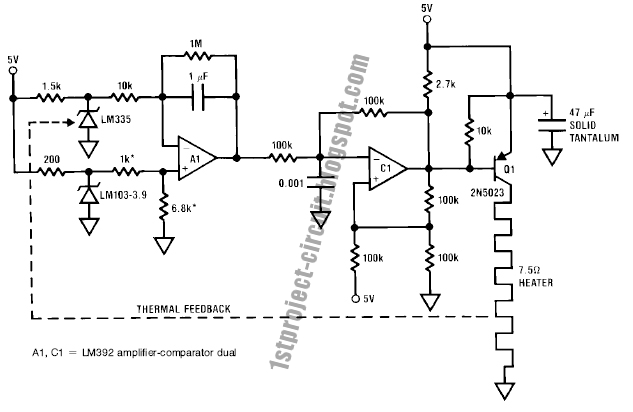
This is the design circuit for control the temperature that is will temperature-control an oven at 75 degrees Celcius. This is the figure of the circuit.


This is ideal for most types of quartz crystals. 5V single supply operation allows the circuit to be powered directly from TTL-type rails. A1, operating at a gain of 100, determines the voltage difference between the temperature set point and the LM335 temperature sensor, which is located inside the oven. The temperature set point is established by the LM103-3.9 reference and the 1k-6.8k divider. A1's output biases C1, which functions as a pulse width modulator and biases Q1 to deliver switched mode power to the heater. When power is applied, A1's output goes high, causing C1's output to saturate low. Q1 comes on and delivers DC to the heater. When the oven warms to the set point, A1's output falls and C1 begins to pulse width modulate the heater in servo control fashion. In practice the LM335 should be in good thermal contact with the heater to prevent servo oscillation. [Schematic’s source: National Semiconductor Notes]

Stepper Motor Controller Circuit

|

This is a circuit for motor stepper controller. A stepper motor controller is needed to run a stepper motor, since a stepper motor cannot work by just connecting it to a power supply. To program a stepper motor to make a complex movement, we usually need a micro controller. This is the figure of the circuit.


This stepper motor controller circuit is still need an external input. If we look at the table, the input pattern is similar to a 2 bits binary counter. If you have an up-down binary counter, then you get a forward-reverse control for your stepper motor. This circuit is very simple design.

Phase Control

|

This is a phase control circuit that can be used to control the power delivered to an AC load. The phase control circuit is to control the AC waveform, cutting the cycle to give full cycle, half cycle, zero cycle, or somewhere in between. This circuit is similar to a dimmer circuit, but the switching is synchronized with the zero crossing of the waveform. This is the figure of the circuit.


The benefit of switching the power in zero crossing condition is that the triacs doesn’t suffer power dissipation, thus increasing the overall efficiency. This phase control circuit is suitable for brushed AC motor, heater filament, or incandescent lamps. The integrated circuit, U208B, is designed as a phase control circuit in bipolar technology with internal supply-voltage monitoring. As the voltage is built up, uncontrolled output pulses are avoided by internal monitoring. Furthermore, it has internal-current and voltage synchronization. It is recommended as a low cost open-loop control.

Powered By Blogger
 

©2009 Project Circuit Design | Template Blue by TNB