Project Circuit Search

Custom Search
WELCOME To PROJECT CIRCUIT DESIGN

Sponsor Link

Showing posts with label Lighting. Show all posts

Discrete Running Flashing LED Circuit

|


This is a circuit for Discrete Running LEDs circuit. This circuit gives a chasing pattern like the running LEDs display in video shops. This is the figure of the circuit;


When the power is applied to this circuit, all transistors will try to come on at the same time. However, some will get a different turn-on current because of the exact value of the 22u electrolytics, and some will be faster due to their internal characteristics. The circuit start reliably because of the last 22u that delay the voltage-rise to the base of the first transistor. This circuit can be extended to any number of odd stages.

Infra Red Wireless Door Monitor Circuit

|

This is a design circuit for door monitor project uses an infrared beam to monitor door & passageways or any other area. The principle operation of this circuit is when the beam is broken a relay is tripped which can be used to sound a bell or alarm. Suitable for detecting customers entering a shop, cars coming up a driveway, etc. The IR beam is very strong. Distances over 25 feet can be monitored. A 12VDC supply is required to power the circuit. A 12V wall adaptor is fine. Provision has been made so that only one power supply needs to be used to power both units. The relay is rated to switch mains voltages. This is the figure of the circuit;


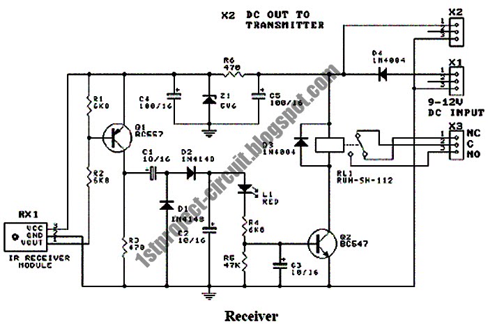
The door monitor transmitter board consists of two square-wave oscillators, one running at approx. 250Hz and the other running at 38kHz. The 38kHz frequency acts as a carrier wave and is required by the IR receiver module on the receiver board. This carrier wave is “ANDed” or modulated by the 250Hz frequency to produce an output signal that contains bursts of 38kHz at a rate of 250Hz. This signal is used to drive an infrared LED. The oscillators are made by using two 555 timer ICs set up as “astable” (free running) multivibrators. IC1 is used for the 250Hz oscillator. Resistor R1 and R2 and capacitor C1 set the frequency. Another 555 chip, IC2, is used for the 38KHz oscillator. Resistors R4 and R5 and capacitor C3 set the frequency. Notice the diodes D1 and D3. This is the figure of the receiver circuit;


The door monitor receiver consists of an IR receiver module that detects the incoming IR beam from the transmitter. The IR signal is used to keep a capacitor charged which in turn holds a relay operated. When the beam is broken the capacitor discharges and the relay releases. An IR receiver/detector module, RX1, is made up of an an amplifier/filter circuit tuned to detect a 38kHz frequency. The output pin is low whenever a 38kHz signal is detected.

When the IR beam is present the relay is operated. Not all Receiver Modules are the same. IR decoder module looks for a manufacturer-specific leader code before it decodes the modulated signal. The door monitor project produces an NEC compatible Leader code. The Kodenshi PIC37043LM and PIC12043LO decoder modules are the ones that are used in this project. If you use the incorrect IR decoder module the relay will not be operated continuously but will drop out after less than a second after power is applied.

Car LED Light Sequencer Circuit

|

This is a design of Car LED Light Sequencer circuit uses a standard 74C164 8 bit shift register as its heart of operation. The 74C164 is also known as a 8-Bit Parallel-Out Serial Shift Register which is a monolithic complementary MOS (CMOS) integrated circuit. These 8-bit shift registers have gated serial inputs and clear. Each register bit is a D-type master/slave flip-flop. This is the figure of the circuit;


Data is serially shifted in and out of the 8-bit register during the positive going transition of clock pulse. Clear is independent of the clock and accomplished by a low level at the clear input. It has a wide supply voltage range from 3V to 15V DC. The input data goes to the serial inputs at pin 1 and 2 which are connected to VCC of the circuit. When pins 1 and 2 are high, the data moves one step forward with each clock pulse. As shown in the diagram above, the outputs are pins 3-6 and 10-13. The data flows from output 1 to 2 to 3... to 8 with each positive edge of the clock pulse. The data can be cleared to zero by putting a momentary low input at pin 9.

Animated LED for Bike Turning Signal Circuit

|

In this circuit, we can make animated LED for bike turning signal. The Led will blink from the right (LED 1) to the left side (LED 5). This is the figure of the circuit;


You must build the second unit to give the complete left and right t urn signal. For the right turn signal, arrange the LEDs so they blink from the left to the right side.

6V Ultra-Bright LED Chaser Circuit

|

This is a design circuit for lights Ultra-Bright LEDs in a sequence and each LED flashes brightly very briefly. The LEDs light-up going around and around since they are mounted in a circle (on a CD), then they pause before chasing again. The very brief flash of each LED (15ms) and the pauses (1 second) reduce the average current so the battery should last a long time. This is the figure of the circuit.


At maximum speed, the LEDs don’t appear to flash, instead they appear to move from one lighted one to the next, around and around. They rotate completely for 4 rotations in two seconds, and then turn off for a one second pause then repeat the sequence. At a lower speed, the number of rotations before the pause is less. It will do three rotations, two or even only one rotation at its slowest speed. A sequence of rotations starts with LED #2 and end with LED #9. The CD74HC4017N high-speed CMOS IC is rated for a maximum supply voltage of 7V. It is rated for a maximum continuous output current of 25mA. In this project, the maximum supply voltage is 6.4V with brand new battery cells and the 24mA output current is so brief that the IC runs cool. The MC14584BCP* IC (Motorola) is an ordinary “4XXX series” 3V to 18V CMOS IC, with a very low operating current and low output current. Its extremely high input resistance allows this project to use high value resistors for its timers and oscillators, for low supply current. Its 6 inverters are Schmitt triggers for simple oscillators and very quick switching.

Part:
Battery: Four AA alkaline cells.
Battery life:
Minimum speed and brightness 2.3 years
Medium speed and brightness 1 year
Minimum speed, maximum brightness 4.1 months
Maximum speed and brightness 3.8 weeks

Brightness: controlled with Pulse width Modulation, from off to extremely bright (4000mcd).
Stepper speed: 2 LEDs/sec to 2 revolutions/sec.
Pulse Width Modulation frequency: 3.9KHz.
LED current: 24mA pulses.
LED voltage drop: 3.2V at 24mA. Blue, green and white Ultra-Bright LEDs are suitable.
Minimum battery voltage:
<3v,>

Powered By Blogger
 

©2009 Project Circuit Design | Template Blue by TNB