Project Circuit Search

Custom Search
WELCOME To PROJECT CIRCUIT DESIGN

Sponsor Link

Showing posts with label Temperature Measurement. Show all posts

Electronic Thermometer Circuit

|

This is an electronic thermometer using an inexpensive silicon transistor as the temperature sensor. This circuit is based on LM112 op amp. This is the figure of the circuit;


This circuit can provide better than 1§C accuracy over a 100§C range. The emitter-base turn-on voltage of silicon transistors is linear with temperature. If the operating current of the sensing transistor is made proportional to absolute temperature the non-linearly of emitter-base voltage can be minimized. Over a b55§C to 125§C temperature range the non-linearly is less than 2 mV or the equivalent of 1§C temperature change. An LM113 diode regulates the input voltage to 1.2V. The 1.2V is applied through R2 to set the operating current of the temperature-sensing transistor. Resistor R4 biases the output of the amplifier for zero output at 0§C. Feedback resistor R5 is then used to calibrate the output scale factor to 100 mV/§C. Once the output is zeroed, adjusting the scale factor does not change the zero.

[Circuit source: National Semiconductor Notes]

Thermistor Stabilized Circuit

|

This circuit is very similar to the lamp stabilized, but can be expected to have better distortion figures. This circuit is based on transistor. There is more amplitude bounce with the thermistor because it has a longer thermal time-constant, but this contributes to its lower distortion. This is the figure of the circuit.


As can be seen, it is very similar to the previous circuit, but the feedback impedance is higher. This will also help lower the circuit's distortion, but as I stated earlier, the thermistor is not easy to get.

Temperature Controller Circuit

|

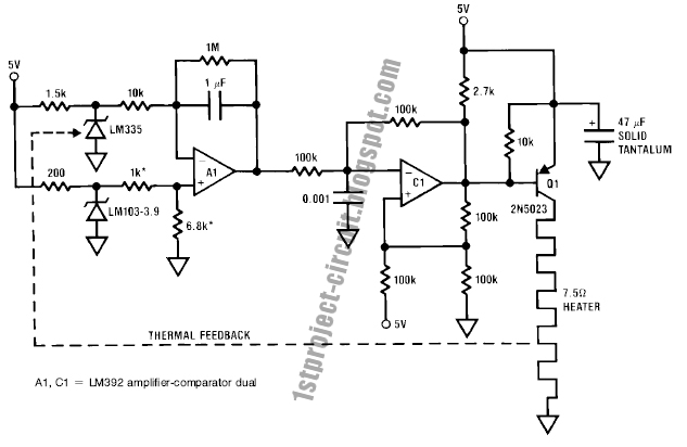
This is the design circuit for control the temperature that is will temperature-control an oven at 75 degrees Celcius. This is the figure of the circuit.


This is ideal for most types of quartz crystals. 5V single supply operation allows the circuit to be powered directly from TTL-type rails. A1, operating at a gain of 100, determines the voltage difference between the temperature set point and the LM335 temperature sensor, which is located inside the oven. The temperature set point is established by the LM103-3.9 reference and the 1k-6.8k divider. A1's output biases C1, which functions as a pulse width modulator and biases Q1 to deliver switched mode power to the heater. When power is applied, A1's output goes high, causing C1's output to saturate low. Q1 comes on and delivers DC to the heater. When the oven warms to the set point, A1's output falls and C1 begins to pulse width modulate the heater in servo control fashion. In practice the LM335 should be in good thermal contact with the heater to prevent servo oscillation. [Schematic’s source: National Semiconductor Notes]

Linear Platinum RTD Thermometer Circuit

|

This is the design for a thermometer. This circuit is work with based on LM392. The IC is used to provide gain and linearization for a platinum RTD in a single supply thermometer circuit which measures from 0 degrees C to 500 degrees C with g 1 degrees C accuracy. This is the figure of the circuit.


Q1 functions as a current source which is slaved to the LM103-3.9 reference. The constant current driven platinum sensor yields a voltage drop which is proportionate to temperature. A1 amplifies this signal and provides the circuit output. Normally the slight nonlinear response of the RTD would limit accuracy to about g3 degrees. C1 compensates for this error by generating a breakpoint change in A1's gain for sensor outputs above 250 degrees C. When the sensor's output indicates 250§C, C1's ``a'' input exceeds the potential at the ``b'' input and C1's output goes high. [Circuit’s source: National Semiconductor Notes].

Powered By Blogger
 

©2009 Project Circuit Design | Template Blue by TNB