


This is a design circuit for door monitor project uses an infrared beam to monitor door & passageways or any other area. The principle operation of this circuit is when the beam is broken a relay is tripped which can be used to sound a bell or alarm. Suitable for detecting customers entering a shop, cars coming up a driveway, etc. The IR beam is very strong. Distances over 25 feet can be monitored. A 12VDC supply is required to power the circuit. A 12V wall adaptor is fine. Provision has been made so that only one power supply needs to be used to power both units. The relay is rated to switch mains voltages. This is the figure of the circuit;

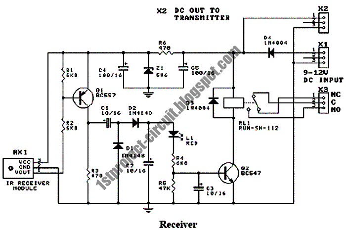
The door monitor transmitter board consists of two square-wave oscillators, one running at approx. 250Hz and the other running at 38kHz. The 38kHz frequency acts as a carrier wave and is required by the IR receiver module on the receiver board. This carrier wave is “ANDed” or modulated by the 250Hz frequency to produce an output signal that contains bursts of 38kHz at a rate of 250Hz. This signal is used to drive an infrared LED. The oscillators are made by using two 555 timer ICs set up as “astable” (free running) multivibrators. IC1 is used for the 250Hz oscillator. Resistor R1 and R2 and capacitor C1 set the frequency. Another 555 chip, IC2, is used for the 38KHz oscillator. Resistors R4 and R5 and capacitor C3 set the frequency. Notice the diodes D1 and D3. This is the figure of the receiver circuit;

The door monitor receiver consists of an IR receiver module that detects the incoming IR beam from the transmitter. The IR signal is used to keep a capacitor charged which in turn holds a relay operated. When the beam is broken the capacitor discharges and the relay releases. An IR receiver/detector module, RX1, is made up of an an amplifier/filter circuit tuned to detect a 38kHz frequency. The output pin is low whenever a 38kHz signal is detected.
When the IR beam is present the relay is operated. Not all Receiver Modules are the same. IR decoder module looks for a manufacturer-specific leader code before it decodes the modulated signal. The door monitor project produces an NEC compatible Leader code. The Kodenshi PIC37043LM and PIC12043LO decoder modules are the ones that are used in this project. If you use the incorrect IR decoder module the relay will not be operated continuously but will drop out after less than a second after power is applied.

The door monitor transmitter board consists of two square-wave oscillators, one running at approx. 250Hz and the other running at 38kHz. The 38kHz frequency acts as a carrier wave and is required by the IR receiver module on the receiver board. This carrier wave is “ANDed” or modulated by the 250Hz frequency to produce an output signal that contains bursts of 38kHz at a rate of 250Hz. This signal is used to drive an infrared LED. The oscillators are made by using two 555 timer ICs set up as “astable” (free running) multivibrators. IC1 is used for the 250Hz oscillator. Resistor R1 and R2 and capacitor C1 set the frequency. Another 555 chip, IC2, is used for the 38KHz oscillator. Resistors R4 and R5 and capacitor C3 set the frequency. Notice the diodes D1 and D3. This is the figure of the receiver circuit;
The door monitor receiver consists of an IR receiver module that detects the incoming IR beam from the transmitter. The IR signal is used to keep a capacitor charged which in turn holds a relay operated. When the beam is broken the capacitor discharges and the relay releases. An IR receiver/detector module, RX1, is made up of an an amplifier/filter circuit tuned to detect a 38kHz frequency. The output pin is low whenever a 38kHz signal is detected.
When the IR beam is present the relay is operated. Not all Receiver Modules are the same. IR decoder module looks for a manufacturer-specific leader code before it decodes the modulated signal. The door monitor project produces an NEC compatible Leader code. The Kodenshi PIC37043LM and PIC12043LO decoder modules are the ones that are used in this project. If you use the incorrect IR decoder module the relay will not be operated continuously but will drop out after less than a second after power is applied.


0 comments:
Post a Comment